Camera node
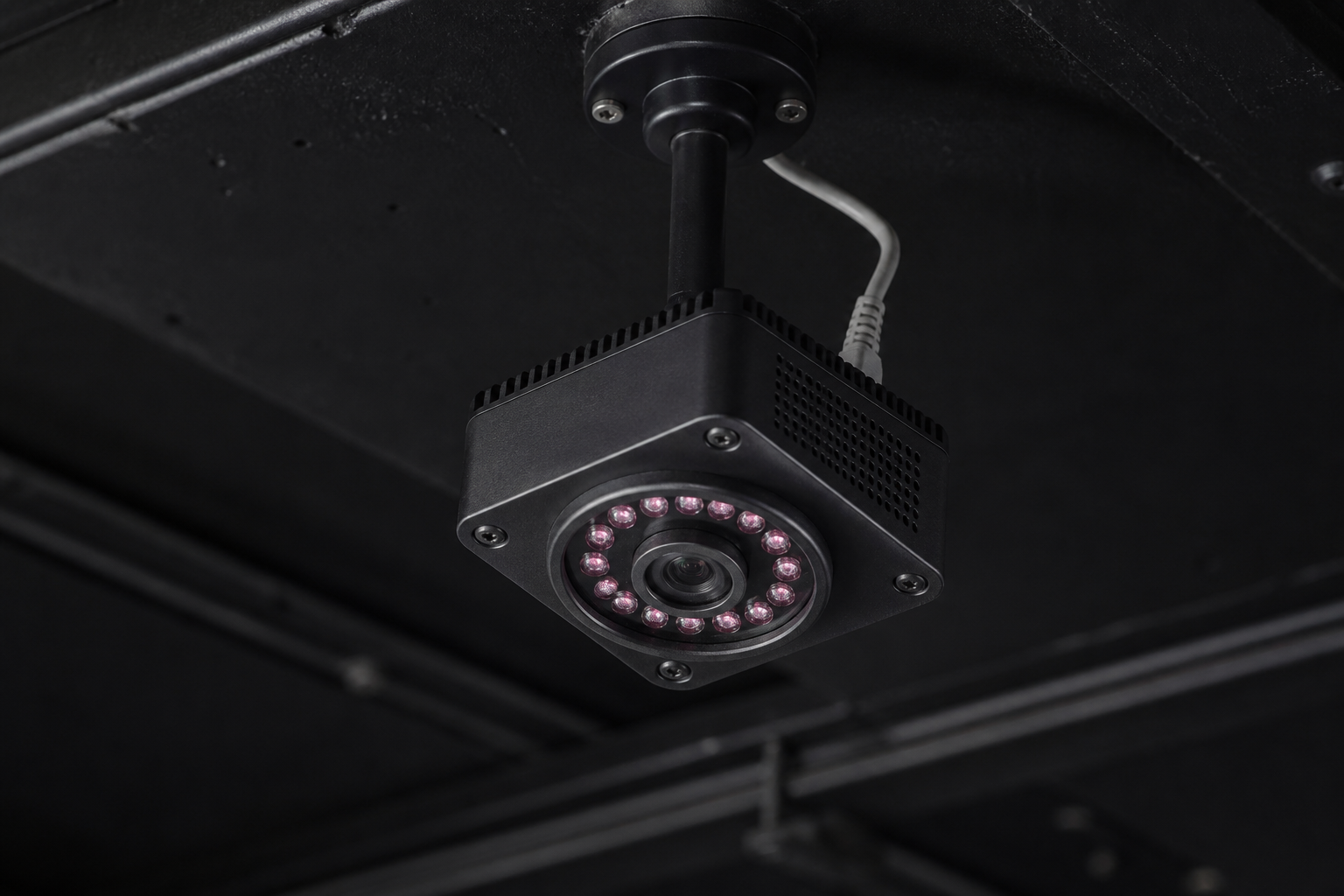
Ceiling IR + 850 nm illuminator — optical v2.
Engineering

Camera node — parts & construction v2 optical
One self-contained ceiling node = Raspberry Pi + global-shutter camera + co-located 850 nm illuminator. Nodes free-run — no sync wiring anywhere. Build 1–2 nodes first for bench gates G0–G2; buy the remaining 4–6 only after they pass.
Shopping list — per node (×4–6 for v2)
| Part | Spec / why | Where | CZK |
|---|---|---|---|
| Raspberry Pi 4B 4 GB (or Pi 5) | capture + on-node blob detect @ 100 fps | RPishop | ~1,550–2,100 |
| Arducam OV9281 NoIR global shutter (CSI, M12 mount) | 1 MP mono; global shutter = no motion smear on a swung wand | Botland PL / RPishop | ~1,100–1,400 |
| M12 lens, ~90–100° HFOV | coverage at 4 m ceiling; fixed focus, locked | RPishop | ~150–320 |
| 850 nm bandpass filter (M12 thread or insert) | rejects WS2815 / DMX / house light; passes illuminator + retro return | TOWIN / AliExpress EU | ~230 |
| 850 nm CCTV illuminator, ~10 W, 60–90° beam | continuous ON; mounted ≤10 cm from the lens | CCTV suppliers approx | ~500–1,500 |
| PoE+ splitter (802.3at → 12 V illuminator + 5 V USB-C Pi) | one Cat6 carries data + power for the whole node | i4wifi / Alza approx | ~600–900 |
| Ball-joint CCTV bracket + enclosure | rigid aim — a bumped camera invalidates calibration | CCTV suppliers / 3D print | ~300–700 |
| Cat6 run to PoE+ switch | homerun per node, wired backbone | installer approx | per metre |
| ≈ per node | ~4,500–6,500 |
4–6 nodes ≈ ~25–35k CZK budgeted (parts math 18–39k by node count/spec; budget covers the typical 5–6-node build incl. mounts + spares), plus ~8k PoE/cabling — matches the v2 sparse optical budget in the BOM. Bench kit for G0 = one node + retro-taped dowel + tape measure.
Assembly order (per node)
- Bench: Pi + CSI camera, flash node image, verify ~100 fps capture at 200–500 µs exposure.
- Lens: fit M12 lens, focus at 3.5–4.5 m target distance, lock the thread (drop of nail polish).
- Filter: screw in 850 nm bandpass. Sanity check: retro dowel glows in preview, room lights vanish.
- Illuminator: mount ≤10 cm from the lens, boresight parallel. Retro tape returns light in a ~1–2° cone back to the source — an illuminator across the room lights the tape for its own camera, not yours.
- Enclose & label:
camera_id+ district on the housing; mount on ball-joint bracket, aim, then torque hard. - Calibrate: intrinsics on the bench (chessboard), extrinsics on site (PnP against 3+ surveyed floor points); register in
cameras.json.
Aiming — not straight down
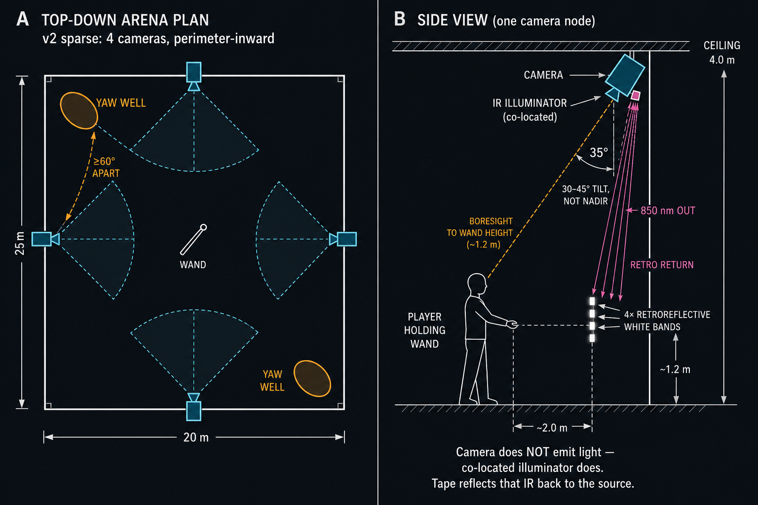
Default tilt: 30–45° off vertical, perimeter-inward. A nadir (90°, straight-down) camera sees a raised wand end-on — the band pattern collapses toward a single blob and that camera drops out exactly during dramatic casts. A tilted camera keeps the shaft near-perpendicular to its line of sight for both horizontal and raised poses.
Rule of thumb: the pattern is unusable when the shaft points within ~15° of the camera axis — so cover each yaw well with two nodes at different bearings (≥60° apart in azimuth). At a 4 m ceiling and 30–45° tilt, the boresight meets wand height (1–1.5 m) about 1.5–3 m from the mount — aim that point at the centre of the district.
Nadir mounts are fine as fill over open floor where wands are mostly horizontal; never as the only view of a district.
How the light path works
The camera emits nothing. Each node has a separate 850 nm CCTV illuminator bolted next to the lens (continuous ON). That IR hits the Scotchlite bands; retro tape returns it in a narrow cone back toward the source — so the camera (≤10 cm away) sees bright white strips while ordinary surfaces stay dark. An 850 nm bandpass on the lens rejects almost all visible light (house lights, tip RGB, DMX, WS2815).
Visible LEDs on the wand tip are VFX only — they do not power tracking.
Smart-obstacle LED straps — safe?
Usually no — they will not destroy tracking if they stay visible-spectrum RGB (WS2815 / WS2812) and the 850 nm bandpass is fitted. The filter is there specifically to ignore those strips. Keep straps on the bottom edge of obstacles (your plan) — that also keeps them out of most tilted FOVs.
What would break it: IR “invisible” LEDs, bare undiffused white LEDs aimed at a camera, or a missing/wrong bandpass. Gate G0 with strips ON is the proof — if the retro dowel still outshines the room, you're fine.