UWB Anchor
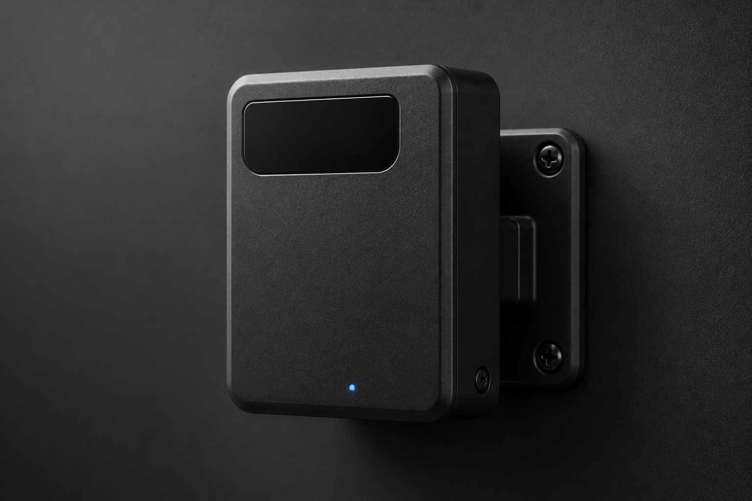
Fixed ranging nodes — ESP32-C6 + DWM3001C.
Engineering

UWB Anchor — fixed ranging node firmware written, room fix pending
Fixed ESP32-C6 + Qorvo DWM3001C nodes provide the UWB infrastructure
that locates every wand (and later every smart obstacle / prop). Typical install:
8–12 anchors around a ~450 m² arena; firmware lives in anchor_sw/.
Firmware focus
web_server— local HTTP on port 80gateway_client— reports ranges upstreamuart_bridge— ESP32-C6 ↔ DWM3001Cota_manager— field updates
UART pinout to DWM3001C matches the wand (see HARDWARE.md and the pinout / J-Link below).
Role in the system
Anchors form the fixed reference frame for TDMA-scheduled ranging. Tags (wands, obstacle PCBs, smart props) range against them; the gateway multilaterates XYZ. Optical cameras are not required for v1 position.
See TDMA for slotting and collision avoidance.
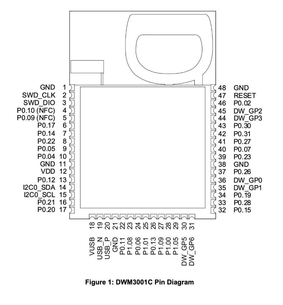
DWM3001C — pinout, J-Link, UART
Same module as the wand. Program the nRF52833 over SWD from a J-Link 10-pin socket; the ESP32-C6 talks UART (115200 8N1, CRLF). Full write-up: HARDWARE.md.
J-Link 10-pin socket · pin face
Two rows of five. Five wires only; unused holes stay open. Socket pin 1 is top-left.
UART — ESP32-C6 ↔ DWM
| ESP32-C6 | DWM3001C | nRF |
|---|---|---|
| TX GPIO 4 | pin 32 UWB RX | P0.15 |
| RX GPIO 5 | pin 34 UWB TX | P0.19 |
| GND | GND | — |
ESP GPIO 4 / 5 — not DWM pin 3 (SWD_DIO) or DevKit header positions 3 / 4.
Flash
Same UWB image on every wand and anchor. Mode (tag vs anchor) is set later over UART, not by a second hex.
cd DWM3001C-starter-firmware-main && make build && make flash